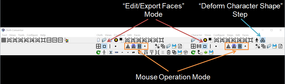
Mouse Operation in View Port
The right mouse button is used to do the follows:
Create and Dissolve regions
A created region is indicated by a overlay of green color, its faces are also called "selected faces". It is created an dissolved by clicking the right mouse button in the viewport as follows:
Clicking On A Not Selected Face
If you click on a not selected face, a region is created as follows depending on the current mouse operation mode:
- Region Grow Mode
A region is created by propagating from the clicked face to neighbor faces until reaching edges on the mesh. The edges are either the original edges of the mesh or created in "Edit Lines" mode.
- Region Grow With Stitching Border Mode
A region is created by propagating from the clicked face to neighbor faces until reaching edges or stitching faces on the mesh.
- Face Group Mode
A region is created by selecting all faces of the face group containing the clicked face.
- Region Grow Off Mode
A region is created using the clicked face only.
Clicking On A Selected Face
The region containing the face is dissolved.
Clicking On Viewport Background
If you click on the viewport background, then you can create multiple regions by drawing a rectangle or polygon to enclose any faces of the meshes:
-
Drawing A Rectangle
After clicking the button, keeping the button pressed and moving the mouse will draw a red rectangle.
-
Drawing A Polygon
After clicking the button, releasing it and moving the mouse to another position and then clicking the button again will draw a red line between the two clicked positions; by drawing a few lines and finally clicking on a previously clicked position will create a red closed polygon.
You can cancel the operation by clicking on the previously clicked position twice again.
Regions may be overlapped.
If Region Grow Mode is set to the Face Group Mode, all faces of the face groups containing the selected faces are selected.
Adjust Vertex Positions
If you click on a face of mesh while pressing the "Ctrl" button on keyboard, then move the mouse pointer horizontally while keeping the two buttons pressed, the positions of the vertices around the clicked point are moved along their normal directions.
The adjusted vertices is limited using the configuration parameters radius and depth, and the adjusting range is limited by the configuration parameter height, as shown in the following figure.
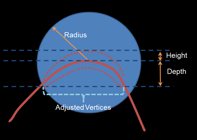
If there are vertices selected, then the adjusted vertices is further limited to the selected only.
The left view port shows face selection and edge editing if both the middle and right view ports are in either "Edit Faces" or "Edit Edges" mode.